

Seeing under salt is not the only way more azimuths may benefit seismic imaging. The extra information also facilitates more accurate modeling of complex structures. Their acquisition is complicated and demanding but it's worth it when the result reduces the risk of expensive drilling decisions.
A progression in survey effort from one vessel towing sources and streamers sailing a survey area in two or more directions to several vessels sailing a survey area in two or more directions, some of them possibly only towing sources, represents the operational contrasts between multi-azimuth (MAZ), wide-azimuth (WAZ), and full-azimuth (FAZ) 3D seismic. Historically, the primary motivations were improved seismic illumination of the reservoir below 'penetration barriers' in the overburden and the attenuation of complex coherent noise types that are difficult to remove using conventional signal processing methods. Significant improvements in seismic image quality and associated exploration drilling success have been reported in a wide variety of global settings; typically involving chalk, carbonates or volcanics in the overburden, or regionally extensive and rugose salt cover above the exploration targets. The availability of diverse azimuth information is also essential when building velocity models that incorporate orthorhombic anisotropy. Seismic imaging solutions able to exploit such information often yield significantly different structural representations of the earth, and are critical for derisking expensive drilling decisions.
Key Benefits
- Narrow-azimuth (NAZ) seismic using one vessel towing both sources and streamers is the standard industry approach, but more azimuths for each offset may benefit seismic imaging, target illumination, and the removal of various complex noise—especially in structurally complex settings
- Multi-azimuth (MAZ) uses one vessel to acquire a survey in two or more survey azimuths to primarily improve target illumination
- Wide-azimuth (WAZ) uses two or more vessels to acquire a survey with one survey azimuth, but individual source-receiver azimuth populations increase, and complex noise that obscures seismic images is removed
- Full-azimuth (FAZ) combines MAZ and WAZ principles and provides the optimum combination of target illumination, complex noise removal, and clear seismic imaging in the most challenging survey areas
- PGS has industry-leading vessel efficiency and imaging solutions that enable the most cost-effective execution of any MAZ, WAZ or FAZ project
Defining "Azimuth"
Conventional 3D surveys are acquired using ‘swath’ or ‘race-track’ vessel shooting, wherein the survey has a single line orientation (or ‘survey azimuth’), and a long, narrow spread of streamers are towed by a single vessel. Apart from the front of the streamers (short source-receiver distance, or ‘offsets’), most source-receiver combinations share a relatively limited range of azimuths (the angles between their particular vector and the survey orientation; see figure below). Thus, the subsurface geology is seismically illuminated only from one particular shooting direction. We assume that most coherent noise types are well behaved and we can remove them in processing. We assume that the target illumination is acceptably uniform, and we can produce clean seismic images. Most of the time these assumptions are in the ballpark of truth and our resultant seismic data allow us to achieve our exploration and appraisal objectives.
 Schematic illustration of source-receiver azimuth and offset for a vessel towing an array of streamers. Note that 'azimuth' is also used to define the sail-line orientation; as used in “multi-azimuth”. The rose diagram describes the offset-azimuth distribution for each shot—assumed to be representative of all shots throughout the survey area. The upper right figure shows the generalized distribution of offsets and azimuths throughout a survey area, appropriate to the acquisition strategy being used. The center of the circle represents zero offset, and the outside of the circle represents maximum offset. Each radial spoke represents the source-receiver azimuth. As seen in both the vessel diagram and the rose diagram, there is a much larger range of azimuths available for the shortest offsets than is the case for the largest offsets (far end of the streamer spread), if conventional narrow-azimuth (NAZ) acquisition is pursued.
Multi-Azimuth (MAZ)
As the overburden complexity and heterogeneity increases, especially in a short wavelength sense (much shorter than the streamer spread length), the seismic illumination of the reservoir will become increasingly heterogeneous, with a corresponding degradation of imaging quality and resolution. It follows that if a 3D seismic survey is acquired in complementary directions, the seismic wavefields propagate through the overburden in different ways, and will yield complementary reservoir illumination. Hence, multi-azimuth (MAZ) surveys can either be pursued by acquiring two or more new survey azimuths, typically acquired in the orthogonal direction to the existing survey, or acquiring one (or more) new survey over the top of a legacy survey. The latter option is attractive for areas where a reasonable understanding of the exploration targets already exists. Thus, it is possible to identify locations for quite small, target-specific 3D surveys that will allow an improved (MAZ) seismic image of each specific target.
The acquisition methodology is conventional: A single vessel towing a streamer spread. The processing methodology is mostly conventional: Standard velocity picking and model building, time-domain migration, etc. The first-pass velocity picking will examine whether there are azimuthally dependent differences in the stacking velocities for each survey azimuth, and the subsequent velocity model building can be pursued in a pragmatic and logical manner. If there is evidence of azimuthally dependent velocity effects, either because of lateral velocity gradients, or in the worst case because of azimuthal anisotropic effects (discussed later), then an independent velocity model must be derived for each azimuth cube prior to MAZ summation. It has become standard to build a common reference velocity model for each azimuth cube during the first pass of velocity picking, and then higher-order velocity corrections are picked independently for each azimuth cube, usually including anisotropic corrections.
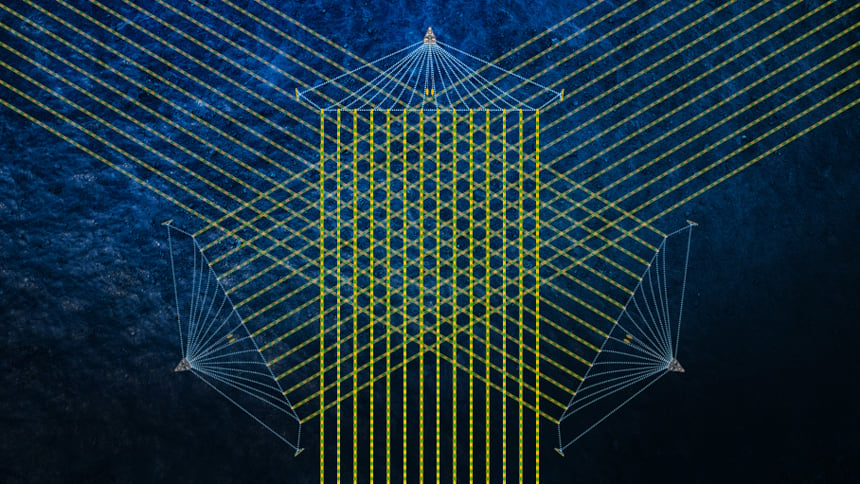 MAZ surveying involves a single vessel acquiring 3D seismic data over the same survey area with two or more survey azimuths.
The first-order benefit of MAZ to data quality is improved target illumination, with a subsequent improvement in spatial event coherency, signal-to-noise content and lateral resolution—provided that local travel time differences (static shifts) can be reconciled everywhere throughout the 3D seismic volumes before they are summed. In the optimum scenario, a MAZ stack can be optimized by selecting on a trace-by-trace and sample-by-sample basis, only those samples from each azimuth cube that would usefully contribute to a coherent output stack event.
Subsurface illumination characteristics vs. survey azimuth and streamer configuration can be qualitatively assessed during pre-survey planning using reasonably accurate 3D velocity models and 3D ray tracing. A somewhat more challenging issue, however, concerns complex coherent noise types not easily addressed using conventional seismic processing—these are discussed below.
The Power of Azimuth Stack
Random noise on conventional (narrow-azimuth or NAZ) data is attenuated by the brute force of stacking across a range of source-receiver offsets in each common midpoint (CMP) gather. The improvement in signal-to-noise content is proportional to the square root of the fold of stack. But, we must usually make simple assumptions when attempting to remove coherent noise in processing. For example, assuming that there is a robust and systematic difference in the moveout of primary signal versus noise on CMP gathers. Or, that the noise can be robustly described by a linear, parabolic, or hyperbolic moveout model. Or, that the traveltime of the noise can be predicted using a simple Earth model, and real noise can thus be attenuated by adaptive subtraction of estimated noise. Surface-related multiple elimination (SRME) predicts multiples from the data itself, assuming that all subsurface reflections occur in a vertical plane below the streamers, and direct arrivals, refraction and various exotic modes of coherent noise are not present in the data. If any of these assumptions are violated, the SRME subtraction process may introduce or exaggerate noise. Likewise, near-surface scattering, focusing and defocusing, and various other transmission effects are generally not acknowledged by the various methods used in an effort to attenuate coherent noise in processing.
Industry experience in recent years, however, backed by 3D modeling studies, demonstrates that if a range of source-receiver azimuths is recorded in addition to a range of source-receiver offsets, then even the most complex coherent noise can be attenuated by the brute force of 'azimuth stack'. The figure below is a comparison of narrow-azimuth and multi-azimuth stack images from the actual MAZ survey acquired in the Mediterranean. Six survey azimuths were combined. Post-survey analysis observed that three survey azimuths would have been optimum, and as intuitively expected, a curve of diminishing return was observed in data quality as the number of survey azimuths contributing to the final result increased.
Experience shows that MAZ acquisition and processing is unable, however, to resolve the most challenging noise problems in areas associated with salt and other rugose and highly reflective 'seismic penetration barriers' in the overburden. In such scenarios, two or more vessels operating simultaneously are required to increase the range of azimuths recorded for each offset. The generic description for such surveys is 'wide-azimuth' or WAZ.
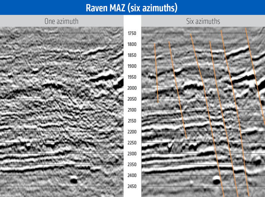 Stack comparison of one survey azimuth (NAZ survey) vs. six survey azimuths (MAZ survey) from the Raven MAZ survey (courtesy of BP). The spatial distribution and resolution of target meandering channel systems was profoundly improved. A curve of diminishing return applies to the improvement in data quality vs. the number of survey azimuths. The cost of each additional survey azimuth decreases in practice as various traces can be ‘borrowed’ from other survey azimuths to reduce infill and coverage requirements.
Wide-Azimuth (WAZ)
Experience shows that MAZ acquisition and processing is unable to resolve the challenging noise problems in salt provinces such as the Gulf of Mexico, Brazil and West Africa. Extra measures must be taken to attenuate the myriad types of complex noise that cannot be addressed in processing. The solution is wide-azimuth (WAZ) acquisition. WAZ surveys historically use two or more vessels to acquire a larger range of azimuths within each shot gather (see figure below). As a consequence, WAZ surveys have the first-order benefit of coherent noise attenuation from the power of azimuth stack, and, as opposed to MAZ surveys, the second-order benefit arises from improved target illumination.
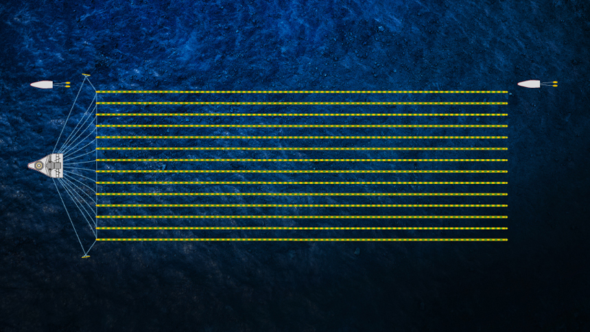 WAZ surveying involves two or more vessels acquiring 3D seismic data over the same survey area, typically with one survey azimuth, but with two or more different relative vessel configurations. In this schematic illustration, one streamer vessel is complemented by two additional source vessels (‘Wide-Azimuth Towed Streamer acquisition, or WATS, the BP-led flavor of WAZ). The survey area is acquired two or more times; each with a different lateral separation between the streamer and the source vessels as the source vessel trajectories are repeated.
Each WAZ vessel configuration such as the example shown schematically in the figure above deploys the streamer and source vessel(s) in a fixed relative geometry during acquisition of the survey area; referred to as a 'tile'. The first tile has the minimum lateral source-streamer separation (close to zero), and each succeeding tile increases this lateral offset by a distance equal to the width of the streamer spread. Thus, two tiles of acquisition simulate acquisition with a streamer spread two times as wide as the one actually being towed; three tiles of acquisition simulate acquisition with a streamer spread three times as wide as the one actually being towed, and so on.
The source positions are exactly repeated for each tile, so the maximum cross-line offset (and maximum source-receiver azimuth range) can be robustly expanded with new acquisition at a later date if required. Note that WATS survey configurations are only one of many possible 'WAZ' survey designs using two or more vessels. While several processing steps must obviously be modified from conventional 3D (NAZ) processing, WAZ processing is robust overall, allowing the use of established tools to incrementally progress from a starting position of noisy data and a highly inaccurate velocity model, to better velocity models and correspondingly higher quality final data. Depth migration is a typical requirement due to the acquisition geometry used, further reinforcing the critical necessity of being able to build a robust processing flow from a starting platform of poor data.
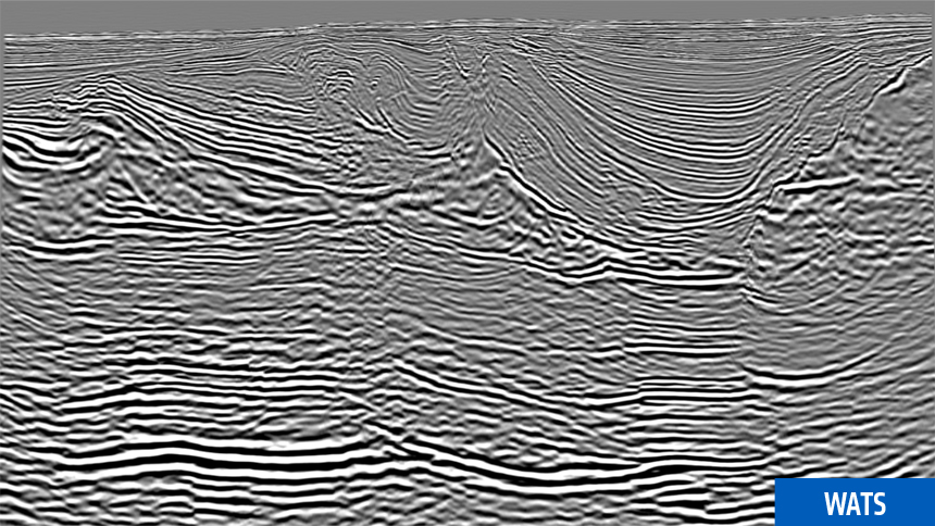
The combination of tiles in processing exploits the brute force power of ‘azimuthal stack’, attenuating much of the complex coherent noise modes that obscured the underlying seismic image of the target geology—such as the GOM example in the image below.
Going Further: Full-Azimuth (FAZ)
In established areas such as the GOM, WAZ acquisition has become standard practice. Exploration WATS (XWATS) with two tiles can be acquired over large areas quite efficiently, thus enabling the confident identification of exploration prospects. If image quality is still inadequate for appraisal or production purposes, new WATS tiles can be acquired to ‘upgrade’ the data set, repeating the shot locations, but using even larger cross-line source-receiver offsets to increase the range of azimuths available for each shot going into processing. Even greater acquisition effort has been used in some locations whereby WAZ surveys are acquired on a MAZ shooting template (refer to the figure below), thereby providing the ultimate combination of target illumination and complex coherent noise attenuation; Full-Azimuth (FAZ).
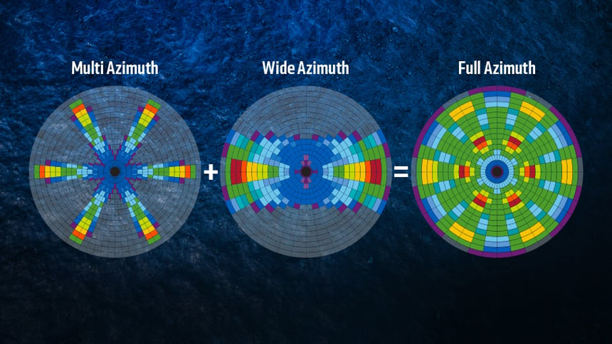 Rose diagrams for a three-azimuth MAZ survey (left), a WAZ survey (center), and a FAZ survey (right). A MAZ survey combines two or more NAZ surveys acquired by a single vessel, but with different survey azimuths. A WAZ survey uses two or more vessels to acquire a larger range of azimuths for each shot. Conventional WAZ shooting acquires parallel lines with one survey azimuth. A FAZ survey applies a WAZ vessel configuration to a MAZ shooting template, and acquires the most continuous range of azimuths for all shots.
PGS acquired the 10 000 sq. km Triton FAZ survey in the Garden Banks and Keathley Canyon areas of the Gulf of Mexico during 2013-2014. Two vessels towed source arrays and large streamer spreads, and an additional three source vessels were used in a five-vessel simultaneous shooting configuration that acquired three survey azimuths, yielded ultra-long offsets of 0-16 km with uniform full-azimuth sampling, and recorded 18-second records. A sophisticated anisotropic depth imaging workflow revealed hitherto-unseen features and geological detail (see figure below).
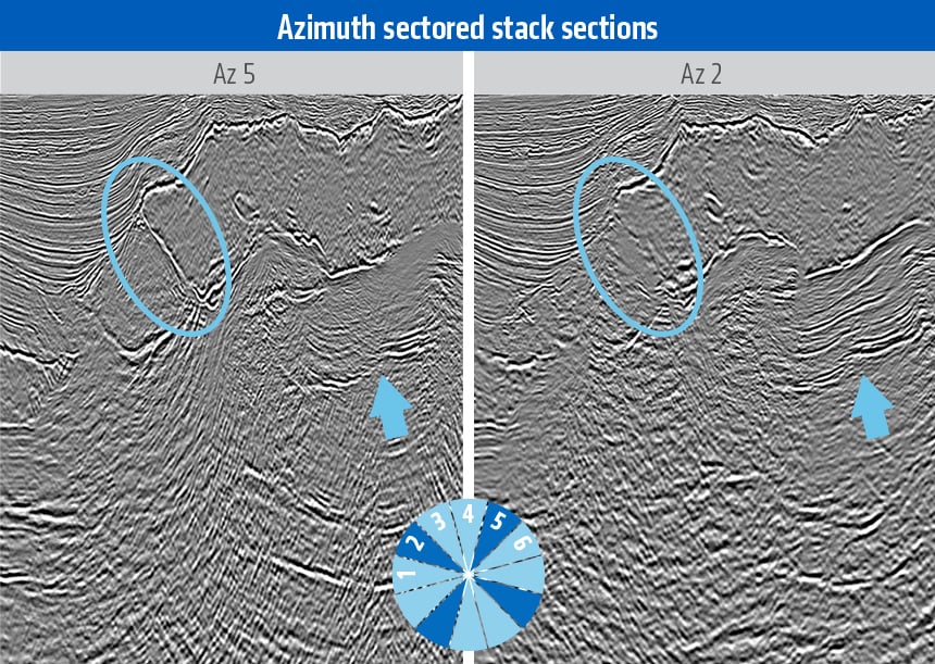 Azimuth-sectored RTM images from the Triton FAZ survey. Note how the structural imaging varies in quality below the salt and at the salt boundaries with different source-receiver azimuth contributions. Full-azimuth (FAZ) acquisition provides many opportunities for optimized velocity model building in structurally complex settings.
The ultimate scale of the projected asset development will be important when determining whether the investment is justified in new MAZ or WAZ surveys, whether those MAZ or WAZ surveys should be designed to be ‘upgradeable’ from meeting exploration to eventually meeting production objectives, and what project timeframe is acceptable. Ultimately, the pre-survey planning dialog may require close collaboration between many different technical and commercial disciplines. In the most challenging scenarios, of course, MAZ or WAZ alone will not suffice, and both target illumination and complex noise attenuation must be optimized. This naturally leads to FAZ, and applies to the fact that a larger range of azimuths than MAZ or WAZ are acquired for all offsets rather than describing a specific acquisition style or strategy.
Correcting for the Effects of Anisotropy
Most hydrocarbon accumulations are located in sedimentary rocks which have been deposited through successive depositional events, resulting in distinct layering. It has always been recognized that this layering imposes an anisotropic fabric into the rocks and that pressure wavefields travel somewhat faster along the layers in comparison to their speed across the layer boundaries (i.e. perpendicular to the layering). It is typical that subsequent tectonic processes caused movement of these sediments from their original position, rotating the original layers into new structures. The addition of fracturing of these sedimentary layers leads to even more complicated anisotropy scenarios.
It is therefore not surprising that by deploying increasingly complex seismic acquisition geometries that capture seismic energy traveling through the earth in a much wider range of directions/azimuths and angles, the anisotropic nature of the subsurface can be far more easily understood and quantified with geometries such as MAZ or FAZ.
A set of theoretical anisotropy models with various simplifications have been developed for velocity model building that aim to describe the observed anisotropic velocity effects, and as a consequence, coherent images can be produced through pre-stack migration using the appropriate anisotropic model assumptions. These models range from more simplistic vertically transverse isotropic (VTI) and tilted transverse isotropic (TTI) models to complex orthorhombic geometries.
The figure below illustrates how the incorporation of orthorhombic anisotropy into velocity model estimation and seismic imaging can significantly alter the value of an imaging project. The depth migrated seismic image on the right has significantly improved the seismic-to-well ties at the deeper target levels, and various geological structural geometries have also changed. Assumptions of isotropy are invalid as data acquired in different directions (survey azimuths) have different velocity moveout functions. By contrast, an appropriate orthorhombic velocity model flattens events in all directions and results in optimum image resolution, quality, and structural positioning.
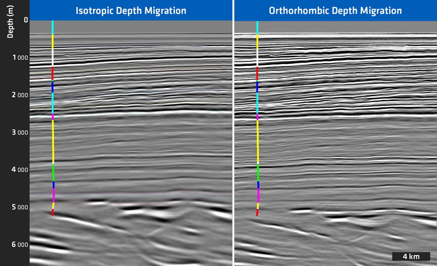 Comparison of isotropic seismic processing and imaging (left) versus orthorhombic anisotropic seismic processing and imaging (right). Note the different event-to-well tie on the right (correct structural positioning) and the improved seismic event focusing on the right (higher resolution).
Again it cannot be underestimated how the complexity of the anisotropic model is bounded by our ability to accurately estimate parameters using surface seismic and/or well data. Any additional azimuthal information may be critical to the accuracy of anisotropic parameter estimation.
Conclusions
A progression in survey effort and investment has been described that is intended to provide an overview of how the acquisition of larger azimuths throughout a marine 3D survey area will improve data quality under various scenarios. Based on the convenience of established narrow-azimuth (NAZ) processing methodologies, the comparative benefits of multi-azimuth (MAZ) and wide-azimuth (WAZ) survey strategies can be contrasted in terms of benefits to target illumination or the attenuation of complex coherent noise. It is assumed that NAZ acquisition and processing is unable to meet the data quality objectives in areas affected by geological barriers to successful seismic imaging. The first-order benefit of MAZ is improved target illumination, and the second-order benefit is coherent noise attenuation. In contrast, the first-order benefit of WAZ is coherent noise attenuation, and the second-order benefit is improved target illumination. Full-azimuth (FAZ) acquisition delivers the ultimate combination of improved target illumination and coherent noise attenuation for towed-streamer surveys but will be reserved for the most challenging scenarios to data quality.
The adoption of orthorhombic velocity model building explicitly depends upon the availability of rich azimuth information for a wide range of offsets throughout the survey area. In practice, this means that at least three survey azimuths are available, although two may suffice in some cases. This requirement lends itself to MAZ acquisition wherein an additional one or two survey azimuths are acquired in addition to an existing survey azimuth. Alternatively, one FAZ survey should satisfy all the requirements for optimal target illumination, coherent noise attenuation, and orthorhombic velocity model estimation. It is encouraging to report that the azimuth story is evolving rapidly and technology solutions to improved efficiency are being continuously delivered. The main ambition of modern pre-survey design efforts is, unsurprisingly, to minimize acquisition effort whilst simultaneously providing the best opportunities for successful processing and imaging.
Contact a PGS expert
If you have a question related to our Marine Acquisition services or would like to request a quotation, please get in touch.