

Wide-tow seismic acquisition maps areas faster but unfortunately it has severe drawbacks in shallow areas. Adding sea-surface reflections increases coverage and data density to deliver more accurate images of the subsurface.
Key SWIM Benefits
- Better imaging of the shallowest layers and shallow drilling hazards
- Better imaging of deeper targets
- Increased data density
- Improved interpretation of complex structures and AVA analysis
The surface of the ocean acts like a huge mirror reflecting the sound we use to create seismic images of geological structures. This unwanted noise can dominate raw seismic recordings and traditionally it has to be removed to reveal the true image of the earth.
PGS SWIM® is an acronym for separated wavefield imaging. It is an algorithm that makes it possible to harness sound waves that reflect off the sea surface. By employing the sensors that record these sea-surface reflections as virtual sources, we access a myriad of additional signals with tremendous angular diversity. These can be used to fill in gaps in survey coverage, and to create strikingly detailed and accurate high-resolution images of the near-surface. They can also assist in producing more reliable velocity models. The key is separating the wavefield, which is a routine process with multi-sensor GeoStreamer® seismic data.
The benefits go beyond significantly increased survey efficiency and gaining a better understanding of the topmost layers. With a better understanding of the overburden, imaging of deeper layers also becomes more accurate. Additionally, we can use these more precise images beneath the seabed to improve the prediction and removal of multiples far deeper in the data volume. In reducing shallow model uncertainty SWIM improves the imaging of deep targets.

SWIM harnesses seismic signals reflected off the sea surface and uses them to deliver extra illumination. By turning the receivers into virtual sources, crossline sampling becomes equal to the distance between streamers. Click to see this in more detail on our SWIM infographic.
Basics
During a seismic survey, sound waves propagate into the earth. As the waves meet first the seabed, and then each layer beneath it, differences in acoustic impedance at each boundary cause some of the sound energy to be reflected upwards again. A signal from the seismic source that is reflected directly back to the seismic receiver is called a primary arrival. However a sound wave does not stop when it’s recorded, it continues upwards. Once it hits the sea surface it is reflected back down again. Seismic signals that have made the journey down and up more than once are called multiples or ghosts and their travel paths can be extremely complex.
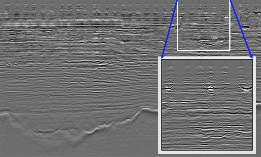
Towing a wide spread of seismic sensors is an efficient method of acquisition. In shallow water, however, much of the energy from the seismic sources is converted to refractions along the sea bottom returning to the surface far from the recording devices. Worst case, there may be no reflections from the seabed or the shallow subsurface, resulting in no imaging of these parts. The recorded data is beset with a telltale footprint of coverage gaps, caused by a limitation on angles of reflection between the target and the recording devices in the outer streamers.
The traditional solution is either to increase the density of recording devices or overlap the recording area (denser sail lines). However, the efficiency benefits of the wide-tow acquisition are then lost.
SWIM for Cover
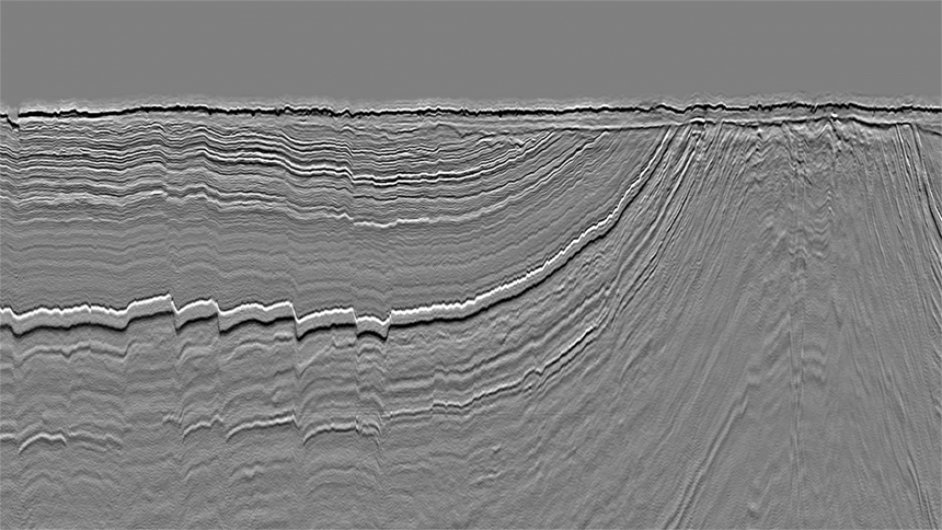
In separated wavefield imaging (SWIM), the sea-surface reflections are treated as bona fide elements of the recorded wavefield. These down-going reflections may be much further away from the vessel than the towed source, and once they have been recorded, they can be used to image the same geological interfaces as the primary reflections from a far greater set of angles – both near and far. The result is more angular diversity in the dataset, with increased lateral coverage and richer illumination of the shallow targets.
The path illuminated by the SWIM image can be the full width of the receiver spread, up to twice as broad as the coverage with primaries only. The depth to which sea-surface reflections can be imaged beneath the seabed is roughly equivalent to the total width of the recording spread.

We seldom look for oil and gas in the top 1500 m of the subsurface, so what is all the fuss about? The answer lies in depth processing. If you are interested in imaging deeper targets and are investing in depth processing, then the success of your project will require an accurate velocity model. You have to solve the shallows to reveal the deep. To achieve accuracy, the model must be calculated and constructed iteratively, from the seabed down to the target. Estimates describing deeper layers depend on the fidelity of shallow data. Accurate depth imaging also depends on the removal of unwanted multiples to reveal the true signal. SWIM shallow layer detail provides ideal input for data-driven multiple removal methods such as 3D SRME.-
Assuming your project is successful, there is an added incentive. High-resolution shallow 3D images provide early intelligence about drilling hazards: channels and structures that can cause a borehole to collapse, or gas that might cause a blowout.
SWIM in the Barents Sea
Sometimes, however, the targets are very shallow. A recent full-scale SWIM study was run on a project from the northern area of what was formerly the disputed zone between Norway and Russia in the Barents Sea. The exploration teams were seeking to uncover shallow opportunities on this northern frontier. It is an area with no well data. Several scientific papers on this project are accessible from the links below. The study combined full waveform inversion (FWI) and SWIM imaging to produce striking improvement in shallow imaging with amplitude versus angle (AVA) compliant results.
A total of 10 200 sq. km of GeoStreamer seismic was acquired in the so-called Barents Sea Southeast (BSSE) during the summers of 2014 and 2015. A tight seasonal weather window compounded by aggressive deadlines meant that acquisition efficiency was the priority. Two surveys were acquired using Ramform vessels and GeoStreamer technology, towing first 10 then 12 streamers, variously 6 and 7 km long, and both 75 m apart, at various tow-depths between 15 and 25 m. The relatively dense spreads were designed to improve the illumination of shallow targets, as one of the main plays in BSSE has targets in the first 1 km beneath to the surface.
The wide-tow spread increased efficiency but the large offset between the seismic source and the recording devices on the front of the outer streamers produced the usual “footprint” holes in the data, as the angles of reflection from shallow layers are wide of these receivers. This affects data in the layers from the seafloor down to around 300 – 400 m. The footprint appears as stripes throughout the dataset, obscuring vital information.

In contrast, SWIM imaging gathers a multitude of data points using sea-surface reflections as new virtual sources, in addition to the primary signals, containing excellent illumination of all angles for these depths. These data were relied upon as the basis for AVA studies and seismic inversion of the shallow data to scout for direct hydrocarbon indicators (DHI). Intercept and gradient results, another staple for exploration departments, are also excellent after SWIM processing of the data.
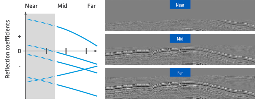
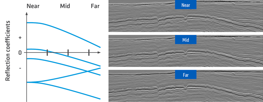
AVA information cannot be confidently extracted from primaries alone due to the lack of near-angle data. By filling in the gaps, SWIM imaging enables accurate AVA analysis for lithology and fluid prediction without well data.
The SWIM data, plus an additional ultra-low frequency model were then used for advanced imaging. Full waveform inversion (FWI) was used as the initial model to generate absolute elastic impedances (acoustic impedance and Vp/Vs) enabling the mapping of hydrocarbon anomalies.
SWIM for Results
In the shallow water environment of the Barents Sea, SWIM is delivering on its promises. Excellent imaging of near-surface targets has been achieved in conjunction with efficient data acquisition techniques, thanks to separated wavefield imaging. The accurate and dependable high-resolution images of the near-surface have been used to analyze the potential of hydrocarbon accumulations, providing crucial input to oil companies’ license round application processes.
Contact a PGS expert
If you have a question related to our Imaging & Characterization services or would like to request a quotation, please get in touch.