

The theory of forward and inverse problems was formalized at the beginning of the 20th century and the math of FWI was published in the early 1980s. Yet it took 30 years before the first commercial applications in 3D. Growing computer power and increasingly complex FWI algorithms are creating more accurate earth models.
- Full Waveform Inversion is a velocity model-building tool
- Earth models are refined by minimizing the difference between recorded data and the modeled data
- Historically only refractions were used and penetration depth was limited
- PGS FWI uses the full wavefield for deeper modeling
Full waveform inversion (FWI) has been hailed as the harbinger of a revolution. In truth, many small but significant steps have brought it where it is today. Early implementations of FWI used transmitted waves, generating accurate high-resolution models in shallow water. Historically, the lack of long offsets and ultra-low frequencies made inversions beyond shallow depths challenging.
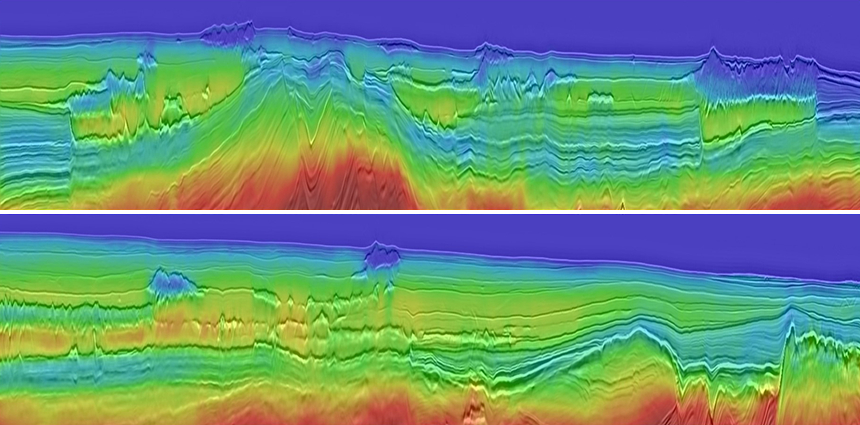
Case Study: Shallow Near-surface Features
Accurate model building with reflection tomography is tricky in shallow water environments. Data diversity is poor and short wavelength, near-surface, velocity contrasts can break the high-frequency assumptions of ray-tracing methods.
The first example shows a shallow water application of FWI. It resolves near-surface features and reduces seismic imaging uncertainty in an area with complex overburden heterogeneities. Unresolved, small, near-surface channels and gas impact the image quality. The velocity varies on a short wavelength and there is a lack of data. As a result, models built with reflection tomography cannot capture the detail required to resolve the imaging challenges that impact the overburden and shallow targets.
The PGS FWI model resolves the complex velocity variations, removing the imprint of a complex overburden channel system that impacted the accurate volumetric measurements at the target interval.
One Small Step at a Time
FWI is routinely applied in shallow water environments. By adapting FWI’s sensitivity kernel to enable the use of the full seismic wavefield for velocity updates, today PGS accommodates ever deeper FWI updates. Using both transmitted and reflected waves, the dynamically-weighted FWI gradient now enables high-resolution model building deeper than can be achieved by diving waves alone, reducing the dependency on long-offset data.
By using sophisticated regularization schemes to stabilize the inversion space, it is possible to place an extra constraint on the objective function that overcomes limitations of the inversion in the presence of high-contrast bodies. This can also be implemented to reduce parameter leakage in multi-parameter inversion for anisotropic parameter epsilon.
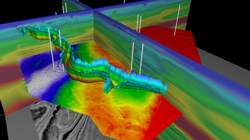
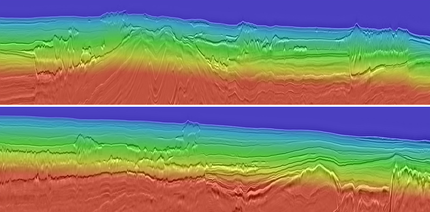
Case Study: Deepwater High-contrast Volcanics
Not all challenges to reflection tomography exist in the overburden. In the second example from west of Shetlands, a reservoir is encased in a high-contrast volcanic interval. The top volcanic generates a recorded refraction, however, the base of the volcanic layer, which is also the top of the reservoir, does not. Snell’s Law infers that a contrast in velocities from fast to slow at such a boundary, and for the offset range used in this acquisition, make transmission FWI difficult. The contrast in velocities also makes reflection tomography challenging because of a lack of data in midpoint gathers. Therefore, the PGS full wavefield FWI was used. Both transmitted and reflected energy contributed and no conditioning or discrimination of these wavefields was required.
The images of the update from FWI show that the intra-volcanic reservoir is captured by PGS full wavefield FWI and is shown as a slowdown (blue) encased within the faster volcanic layer. The same approach has been used for intra- and pre-salt updates on PGS library data from the Santos Basin.
 FWI model differences co-rendered on an inline-crossline intersection. Image courtesy of Siccar Point Energy Ltd, Chevron North Sea Ltd, INEOS, Shell UK and Suncor Energy
New Flavors Abound
As computing power has expanded, so has the seismic frequency range on which FWI is run. While the greatest benefit for model building is achieved from access to relatively low frequencies, increasing the frequency content in FWI helps in reservoir characterization.
Obtaining full-bandwidth, absolute elastic-attributes for lithology and fluid prediction requires a low-frequency model. The lower frequency component required for the modeling can be generated from velocities, assuming they contain sufficient resolution. This reduces the emphasis on the well and seismic information. This can make a vital difference in exploration settings. Less a prior input is an advantage in attribute prediction and ensures that the results of pre-stack seismic inversion are primarily data-driven.
Using a broader frequency content to obtain the FWI model can provide the lower frequency component for elastic property generation. Well information becomes a control point. This allows reservoir geoscientists to confidently derive reliable elastic attributes, such as acoustic impedance and Vp/Vs ratios, away from the well locations.
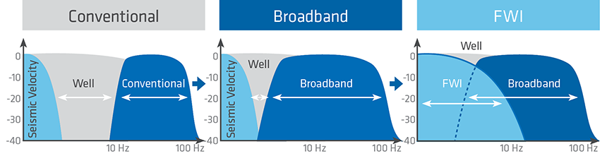 Higher-frequency content in FWI further improves elastic attribute calculations for reservoir characterization and can be combined with broadband data input to minimize the need for well data
Case Study: Multi-layer Prospectivity
An FWI model using seismic data up to 18 Hz was employed as the low-frequency component for elastic property generation of multi-layered prospectivity in the Barents Sea. Accompanied by a mature rock physics model, the high-resolution FWI model and broadband seismic data enhanced by separated wavefield imaging (SWIM) were used to create absolute elastic properties. These attributes were then used to derisk prospects.
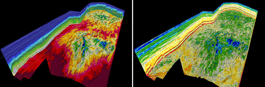 FWI model (left) and the resulting absolute impedance volume (right) from the Barents Sea
Next Steps
The primary challenge for FWI is overcoming the cycle-skipping phenomenon, where waveforms of the modeled data are out-of-sync with the equivalent waveforms from the acquired data. Practical solutions include using the lowest possible signal frequencies or upgrading the starting model for FWI.
In some cases, a multi-scaled approach that slowly increases the frequencies and data selection per iteration can achieve a high-resolution FWI model even in complex geological environments.
PGS is investigating a multitude of approaches to mitigate the cycle-skipping problem, which in turn relaxes the requirements on the starting model for FWI, and reduces the turnaround time required to generate accurate earth models. These include the use of robust norms with more convex behavior for measuring the data misfit, preconditioning the model through data warping, and time-frequency hybrid implementations of the inversion.
Case Study: Carbonate Muds
The Vøring Basin contains a number of challenges for effective model building, including high-contrast carbonate muds called oozes. These are difficult to resolve unless one uses a full wavefield FWI. A combination of transmitted and reflected energy, in an accurate FWI-driven model, can isolate the bodies and counteract the distortion and dimming effects.
The model building was achieved in a short timeframe, as the starting point for FWI was a 1D model comprising four layers. Cycle-skipping was mitigated using a multi-scale approach starting with ultra-low frequencies enabled by deep-tow acquisition. The resulting model isolated the ooze bodies. The migration with the FWI model created a seismic dataset of striking clarity, free of the effects of the ooze.
Roll on the Revolution
FWI is a powerful tool that, since its launch, has been expected to revolutionize seismic imaging. It took 30 years for FWI to become a commercial reality and required the exponential growth of computing power over the last decade to produce FWI algorithms that can deal with the full wavefield, and multi-parameter inversions. In reality, it has been an evolutionary process, not a revolutionary one. Cycle-skipping mitigation remains a problem, and PGS is developing methods to mitigate them. Our ability to create full bandwidth earth models directly from raw seismic data has never been closer.
Contact a PGS expert
If you have a question related to our Imaging & Characterization services or would like to request a quotation, please get in touch.